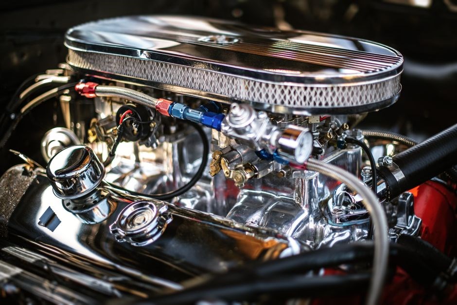
Valve Guide Seal Overview
Valve guide seals regulate oil flow to valve stems, ensuring proper lubrication while preventing excess oil from entering combustion chambers. They maintain engine efficiency, reduce wear, and help control combustion temperature by limiting oil seepage. They also aid in sealing combustion gases.
Definition and Purpose
The valve guide seal is a small, precision‑made component that sits within the valve guide of an internal combustion engine. Its primary definition is to act as a barrier that controls the amount of engine oil that travels from the oil gallery onto the valve stem as the valve opens and closes. By limiting oil flow, the seal prevents excess oil from being drawn into the combustion chamber, which could otherwise lead to fouling of spark plugs, increased fuel consumption, and higher emissions. The purpose of the seal is therefore twofold: first, to provide adequate lubrication to the valve stem and guide to reduce friction and wear; second, to maintain a clean combustion environment by restricting oil seepage. In high‑performance or heavy‑duty engines, the seal’s ability to keep oil out of the combustion chamber is critical for sustaining power output and ensuring long service life. The seal also contributes to the overall sealing integrity of the cylinder head, helping to preserve compression and prevent blow‑by. In summary, the valve guide seal is a small but essential element that balances lubrication needs against the risk of oil contamination, thereby supporting engine reliability and efficiency. These seals are typically made from high‑temperature resistant polymers such as PTFE or fluorocarbon blends, which allow them to withstand the thermal cycling and pressure variations encountered during engine operation. The seal’s geometry—often a tapered or conical shape—ensures a snug fit against the valve guide, creating a seal that can flex slightly to accommodate thermal expansion while still blocking oil flow. Engineers design the seal to maintain a consistent gap between the valve stem and guide, which is critical for accurate oil metering. The proper selection and installation of the seal directly influence the engine’s longevity and performance, making it a key component in engine maintenance schedules. Regular inspection of the seal during routine maintenance can detect wear or deformation early, preventing oil leakage and potential engine damage.
Role in Engine Lubrication
The valve guide seal is the first line of defense against oil migration into the combustion chamber. By creating a controlled barrier between the oil gallery and the valve stem, it ensures that only the precise amount of oil needed for lubrication is delivered. This controlled flow reduces friction, limits wear on the valve stem and guide, and keeps the combustion surfaces clean. In engines with high compression ratios or aggressive cam profiles, the seal’s ability to restrict oil seepage is critical for maintaining optimal combustion temperatures and preventing detonation. The seal also helps keep the valve stem at a consistent temperature, which is essential for maintaining the correct oil viscosity under varying operating conditions. Proper lubrication of the valve stem reduces heat buildup, prevents galling, and extends the life of both the valve and the guide. In addition, the seal’s material properties—often high‑temperature fluoropolymers—allow it to resist oil degradation, maintain flexibility, and withstand the thermal cycling that occurs during engine start‑up and idle. When the seal is worn or damaged, oil can bypass the barrier, leading to excessive oil consumption, fouled spark plugs, and increased emissions. Regular inspection and timely replacement of the seal are therefore integral to engine maintenance programs, ensuring that lubrication remains efficient and that engine performance is not compromised by oil leakage. Overall, the valve guide seal’s role in engine lubrication is to balance the need for protective oil film against the risk of oil intrusion into the combustion chamber, thereby safeguarding engine durability and efficiency!
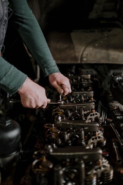
Types of Valve Guide Seals
Engine manufacturers offer two primary seal families: the umbrella seal (SS72823) for older models and the positive stop seal (SS70579‑1) for newer engines. Each design matches specific valve guide dimensions and operating pressures, ensuring optimal oil control and longevity. Rated 2000°F. (high)
Umbrella Seal (SS72823)
The umbrella seal (SS72823) is a classic valve guide seal used in many V8 engines, especially the 454 series through 2000. Its shape resembles an inverted umbrella, providing a broad sealing surface that accommodates variations in valve guide diameter while keeping oil control tight. It fits guides with an outer diameter of 0.615–0.620 inches, ensuring compatibility across many engine blocks. Made from high‑temperature fluorocarbon or PTFE‑based material, it resists harsh oil and combustion environments. Installation is straightforward: slide the seal into the guide, then secure it with a spring retainer. The design allows limited movement, so minor wear does not compromise integrity. Technicians often use compressed air or a rope through the spark plug hole to hold the head while replacing the seal. Properly installed, the SS72823 seal prevents oil leakage into the combustion chamber, reduces blow‑by, and extends valve life by ensuring consistent lubrication. Regular maintenance is critical for engines that have seen heavy use, as worn seals can increase oil consumption and reduce performance;
Verify the seal’s integrity before reassembly, as a compromised seal can lead to oil starvation of the valve stem. Inspect the guide for scoring or burrs that may affect seal seating. When reassembling, torque the valve head bolts to the manufacturer’s specifications to maintain proper head clearance and seal performance.
A calibrated torque wrench ensures bolts are tightened to spec, preventing leaks.
Positive Stop Seal (SS70579-1)
The Positive Stop seal (SS70579-1) was introduced in 2001 for the 8.1‑liter V8, replacing the umbrella design. It features a rigid stop ring that locks the seal in place, preventing axial movement and ensuring a precise oil‑control interface. The ring is made from a high‑grade fluorocarbon compound that tolerates temperatures up to 400°F and resists oil breakdown. Its geometry matches valve guides with an outer diameter of 0.615–0.620 inches, providing a snug fit that eliminates gaps. Installation requires a spring retainer and a calibrated torque sequence; the seal is first slid into the guide, then the retainer is seated, and the valve head bolts are tightened to spec. Because the stop ring is fixed, the seal resists the high‑pressure oil pulses typical of modern engines. This design reduces blow‑by and improves combustion efficiency. Routine inspection is essential: look for cracking, hardening, or oil leakage. Replace the seal after 50,000–70,000 miles or when oil consumption rises. Proper reassembly includes cleaning the guide, checking for burrs, and using a torque wrench to achieve the manufacturer’s bolt torque. A correctly installed SS70579‑1 seal maintains valve stem lubrication, extends valve life, and keeps the engine running smoothly.
Finally, always verify the seal’s integrity with a leak test and ensure the head gasket is in good condition to avoid cross‑contamination. A seal not only protects the valve stem but also contributes to the engine’s longevity and performance and oil.!

Design and Material Considerations
Design focuses on seal geometry, material, and compatibility. Common materials are PTFE and fluorocarbon blends, chosen for high‑temperature resistance and low wear. The seal must match guide OD 0.615–0.620 inches, ensuring a tight fit and preventing oil leakage. Seal integrity vital longevity.
Seal Material (e.g., PTFE, Fluorocarbon)
Valve guide seals are engineered from high‑performance polymers that endure extreme temperatures, high pressures, and aggressive lubricants. The predominant base material is polytetrafluoroethylene (PTFE), prized for its low friction, chemical inertness, and excellent oil‑shedding. PTFE’s inherent softness can, however, accelerate wear under high‑pressure conditions, so manufacturers often blend it with fluorocarbon elastomers such as Viton® or Kalrez® to enhance mechanical strength, improve compression set resistance, and extend service life. Fluorocarbon blends also provide resistance to oxidation and high‑temperature oil degradation, critical for turbocharged engines. In addition to PTFE‑based composites, some seals incorporate silicone or EPDM additives to improve flexibility at low temperatures, ensuring a tight seal in cold climates. Material selection is guided by engine specifications, operating temperature, and oil chemistry. For example, a high‑octane racing engine may require a seal with higher fluorocarbon content to resist oil breakdown, while a diesel engine operating at lower temperatures might benefit from a silicone‑enhanced PTFE blend. Compatibility with the valve guide’s metal surface is crucial; a seal with slight radial expansion can accommodate minor guide wear, preventing oil leakage while maintaining a seal. Finally, manufacturers provide detailed material data sheets that specify hardness (Shore A), compression set, and temperature limits, allowing technicians to match the seal precisely to the engine’s operating envelope. Proper material selection not only preserves oil control but also reduces maintenance intervals and extends overall engine reliability. Fluorocarbon blends resist oxidation, high‑temperature oil degradation,and seallongevity in turbocharged engines!
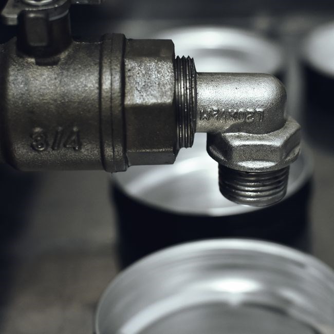
Valve Guide OD Compatibility (0.615–0.620)
Valve guide seals are engineered to fit precisely within a narrow outer‑diameter (OD) window that is critical for maintaining oil control and preventing combustion‑chamber contamination. In most contemporary gasoline engines, the industry standard OD range for valve guides is 0.615 in. to 0.620 in. This range is chosen to accommodate the thermal expansion of the guide material, the radial compression of the seal, and the tolerances of the valve stem. A seal that is too small will compress excessively, leading to premature wear, cracking, or even seal rupture, while a seal that is too large will not engage the guide surface fully, allowing oil to leak past the seal into the combustion chamber or crankcase. The key to successful installation is a meticulous measurement of the guide OD using a calibrated micrometer or digital caliper. Technicians should measure at least three points around the guide circumference to account for any eccentricity or wear that may have occurred over time. Once the exact OD is known, the seal manufacturer’s tolerance chart can be consulted to identify the nominal seal size that matches the measured OD within ±0.001 in. For example, a seal stamped 0.617 in. is designed to fit a guide with an OD of 0.617 in. ±0;001 in., ensuring a uniform contact area and optimal oil film thickness. If the guide OD falls outside the 0.615–0.620 in. window, custom or aftermarket seals may be required. These custom seals can be fabricated from the same PTFE or fluorocarbon blends used in standard seals, but with a modified taper or core diameter to match the unique guide geometry. Proper OD compatibility also allows the seal to accommodate differential thermal expansion between the guide and the seal core, preserving a tight seal throughout the engine’s operating temperature range. Regular inspection of the guide OD after major overhauls is essential, as wear or machining errors can shift the OD, necessitating a new seal. By ensuring that the seal’s OD matches the guide’s OD within the specified range, technicians can guarantee reliable oil control, reduce wear, and extend engine life.
Installation and Service Procedures
Remove the head, clean valves, use compressed air or rope to hold pistons, then pull spring retainers with a hammer and socket. Install new seals, re‑attach retainers with a spring compressor, and torque head bolts per spec; Verify seal fit and torque
Head Removal Methodology
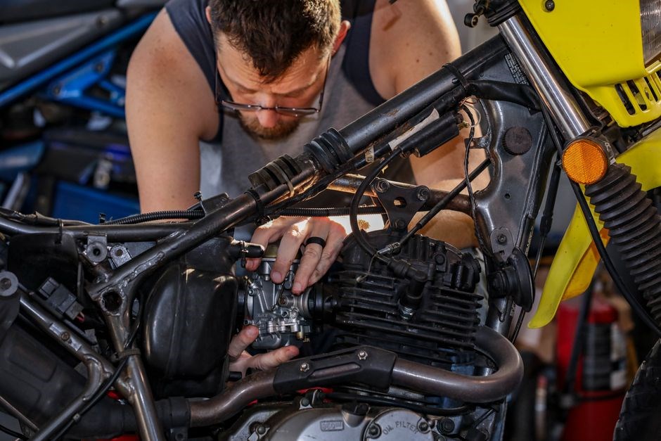
Begin by disconnecting the battery and draining coolant. Remove the intake manifold, exhaust headers, and any ancillary components that obstruct the head. Carefully detach the timing chain or belt, noting gear alignment marks. Use a torque wrench to loosen head bolts in a cross‑pattern sequence, gradually increasing torque to the specified value. Once all bolts are removed, lift the head with a hydraulic jack or a dedicated head puller, ensuring the cylinder head sits on a flat surface to avoid warping. Inspect the valve guides for wear and replace seals before re‑installation. If the engine has a cast‑iron block, apply a thin layer of anti‑seize compound to the head studs to facilitate future removal. Keep a clean work area to prevent debris from entering the combustion chambers. After head removal, clean the valve stems, inspect the camshaft, and verify that the valve guide OD matches the seal specifications (0.615–0.620). Document bolt torque values and any irregularities for service records. Employ a torque angle gauge to verify that each head bolt reaches the required 90° rotation after the initial torque. Use a torque angle gauge to ensure uniform distribution of clamping force across the head. If the engine has a forged block, consider using a block sealant to prevent leaks. Keep a log of the head removal process for future reference. When reinstalling, re‑apply the correct torque sequence and use a calibrated torque wrench to ensure head gasket integrity. Finally, re‑assemble all components in reverse order, re‑check coolant and oil levels, and perform a compression test to confirm proper head seating.
Seal Replacement Techniques (Compressed Air, Rope, Spring Retainer)
When the cylinder head remains on the block, the valve guide seals can be swapped by a few methods that avoid a full head removal. The compressed‑air technique involves directing a steady stream of air into the combustion chamber through the spark‑plug hole. The air pressure temporarily holds the piston in place, preventing the valve stem from moving and allowing the seal to be slid out with a small pry bar or a seal‑removal tool. Care must be taken to keep the air flow steady; a sudden surge can dislodge the piston or damage the head. The rope‑in‑the‑cylinder approach is similar, but instead of air, a length of stiff nylon or steel rope is fed through the plug hole and wrapped around the piston. The rope’s tension keeps the piston stationary while the seal is extracted. This method is useful when a high‑pressure air source is unavailable or when the head is heavily corroded. The spring‑retainer method is employed when the valve stem’s retaining spring is still in place. A spring compressor or a specially designed retainer extractor is used to compress the spring, allowing the retainer to be removed. Once the retainer is out, the seal can be slid out or replaced. After the new seal is seated, the spring retainer is re‑installed, and the spring is re‑compressed with the compressor. Each technique requires a clean work environment; debris can compromise the seal fit. Proper torque settings for the valve stem bolts must be observed after re‑installation to ensure a tight seal. Finally, a leak test with a small amount of engine oil or a pressure gauge confirms that the new seal is functioning correctly before the engine is returned to service.
When using compressed air, a calibrated air gun with a pressure gauge ensures the pressure does not exceed 5 psi, sufficient to hold the piston. For rope insertion, a 3‑inch nylon rope is preferred; tie it to a small weight to maintain tension. The spring retainer extractor has a 1/4‑inch drive and a 3‑inch jaw; align it with the retainer’s slot to avoid cross‑threading. A pressure test at 30 psi for 30 seconds verifies that no oil leaks through the guide. Tools should be cleaned use.
Use a high‑temperature grease on the retainer extractor to reduce wear and ensure smooth operation. After re‑installation, re‑torque the valve stem bolts to the manufacturer’s specifications, then perform a compression test to verify proper sealing.
Common Issues and Troubleshooting
Oil leakage, overlubrication, and seal wear are frequent problems. Inspect seals for cracks, ensure proper torque, and replace when oil seeps past the guide. Check valve guide OD for compatibility. Verify seal integrity with a gauge; replace if needed.!!
Oil Leakage and Overlubrication
Oil leakage and overlubrication are common symptoms of degraded valve guide seals. When seals fail, oil can seep past the valve stem, entering combustion chambers or escaping through the exhaust. This not only reduces compression but also increases fuel consumption and can cause fouling of spark plugs. Overlubrication, on the other hand, occurs when seals allow excessive oil to flow, leading to oil mist in the cylinders and potential detonation. Diagnosing these issues involves a systematic approach: first, inspect the engine for oil residue on spark plugs, valve covers, and intake manifolds. A clean plug indicates proper sealing, while a greasy surface suggests leakage. Next, perform a compression test; low compression on cylinders with high oil residue points to seal failure. Visual inspection of the valve guides can reveal oil stains or wear patterns. If seals are suspected, remove the cylinder head and examine the guides for scratches, scoring, or deformed O‑rings. Replacement of worn seals with the correct type—umbrella or positive stop—must match the valve guide OD (0.615–0.620). Proper torque of the head bolts is critical; under‑torqued bolts can allow seals to flex, while over‑torqued bolts may crush them. After reassembly, a leak test using a pressure gauge can confirm that oil no longer escapes. Long‑term prevention involves maintaining proper oil viscosity, regular oil changes, and ensuring the engine does not run too hot, which can accelerate seal wear. By following these steps, technicians can identify, correct, and prevent oil leakage and overlubrication, preserving engine performance and longevity.
In addition, certain engine designs incorporate oil pressure relief valves that can mitigate overlubrication by venting excess oil. However, if seals are compromised, these reliefs may not function effectively. Technicians should also verify that the valve guide seals are installed with the correct orientation; reversed seals can lead to immediate oil leakage. Finally, monitoring oil consumption during routine service can provide early warning signs; a sudden increase in oil usage often correlates with seal degradation.
Regular documentation of seal replacement dates helps track wear cycles.
Seal Wear and Replacement Timing
Valve guide seals wear gradually due to thermal cycling, oil contamination, and mechanical abrasion. Industry data indicate seals reach critical wear after 30,000 to 50,000 miles, varying with engine load and temperature. A practical schedule is to inspect seals every 25,000 miles for engines and every 40,000 miles for vehicles. Inspection requires removing the cylinder head, cleaning the guides, and checking for oil stains, scoring, or deformation. If the seal’s cross-section has reduced by more than 10 % or the valve stem shows uneven oil film, replacement is warranted. A sudden rise in oil consumption or a drop in compression on a cylinder signals imminent seal failure. When replacing, use the correct seal type (umbrella or positive stop) matching the guide OD (0.615–0.620) and torque the head bolts per manufacturer specs. After installation, perform a compression test to confirm seal integrity. Documenting each replacement in a log helps predict wear patterns and prevents costly engine damage. By following these guidelines, technicians maintain optimal engine performance and extend service life. If oil level drops by more than 0.5 oz per 1,000 miles or compression falls below 90 % of spec, schedule a seal inspection. A 5 % reduction in seal thickness should trigger replacement. By adopting these measures, the risk of engine failure due to seal failure is minimized, ensuring reliable operation over the vehicle’s lifespan Regular service intervals OK!!! ……..